Calibration Wizard
The new version of the FUtracer GUI includes a Calibration Wizard. If you already have any firmware/software version after April 2022 (2.07 or greater), you can use the Calibration Wizard.
Manual Calibration is only useful if you haven’t upgraded yet, and/or prefer things to be more difficult.
Firmware Update
If you have an FUtracer kit purchased after October 2022, then you will have firmware v3.xx which can easily be updated via the FUtracer GUI. All FUtracer v7+ kits ship with upgradeable firmware.

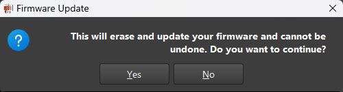
To update your firmware, open the options dialog in the FUtracer GUI, then click “Update FW.” Select Yes if you’re sure you’re ready to update, and then a window will open asking you to select your new firmware .bin file. Select the latest firmware, and the FUtracer will update the firmware for you. Do not power off or disconnect your FUtracer until the process is complete. The FUtracer will restart itself after update, and the GUI status bar will say “Firmware Version Read” or “On chip calibration read OK” or “Ping OK.” Which message depends on the status of your tracer (calibrated or not) and how long you wait (Ping OK appears if you wait long enough).
The current firmware version is v3.02. If you have an older firmware version that cannot be remotely upgraded, you can send your chip in to be updated, or purchase a new firmware chip for $30.
Manual Calibration
Before you can calibrate the FUtracer, you will need to install the GUI. I have preset calibration functions which can be found at the bottom of the tube Type Selection drop-down list.
FUtracer GUI INSTALLATION
WINDOWS:
- 1. Download and unzip FUtracer_GUI.zip into your home directory i.e., \Users\YourName\. This will create a folder named utMax_files. Note: This folder name is mandatory, and the GUI will not function if it is incorrect.
- 2. In the folder utMax_files\tracer_program_files, you will find the executable uTmax.exe. You can create a shortcut and add to your Start menu, if you wish.
Data File
You may be asked to select your tube data file. Browse to the FUtracer_GUI folder and select the data.csv file.
Theme Options
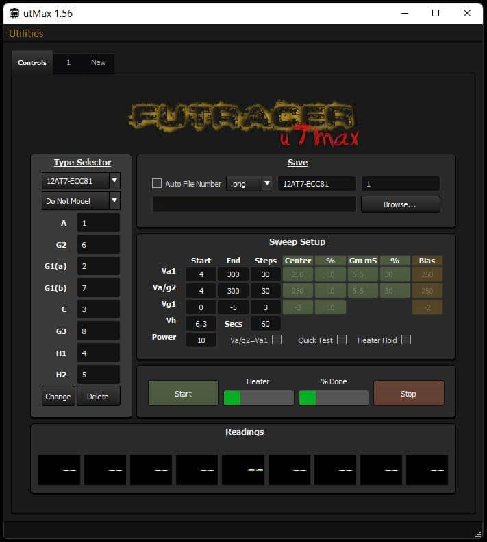
If after installing the GUI there is no theme selected / the GUI looks weird, you may need to select a theme. You can change the them of the FUtracer GUI to one of three options. The default, pictured above, is the “Dark Theme.” There are also options for Darker Theme, or Light Theme.
To change your theme:

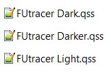
After clicking the “Theme Browser” button, you can choose one of the 3 .qss files listed above to switch themes. If you have css programming skills, you can customize your own theme as well.


The first step in the calibration procedure is already taken care of if you’re using the zip from this site. Modification of the following is only necessary if you’re not building to the standard FUtracer specs.
Default FUtracer Settings:
RaVal=5350
VaMax=400
IaRsense=5.1
IsRsense=5.1
VgMax=50
Firmware=2XX or 3XX (ie. 207 for 2.07, 302 for 3.02 etc. Must be 200 or 300 level for FUtracer)
Safer Current Levels
NOTE: the IaRsense (R45)and IsRsense (R20) resistors by default allow the FUtracer to go to higher currents than what is considered safe for the KSA1156YS. If you wish to play it safer (which is not a bad idea), use 6.8 ohm resistors instead, which will give you a maximum current limit of about 529mA. Then your setting would look like this:
IaRsense=6.8
IsRsense=6.8
If you wish to be even safer and go below the “on paper” limit of the KSA1156YS, you could instead use 7.5 ohm resistors to get under 500mA. Whatever value you choose to go with, it is essential that you enter this value correctly, or your current readings will not be accurate.
Range Check
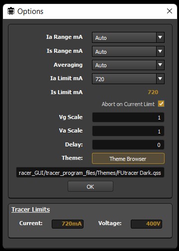
Start uTmax, click Utilities – > Options. Check that the values displayed under Tracer Limits (pictured far right, bottom) correspond to your hardware. If these are not correct exit and check the settings in the cal.txt file.

COM Port
Select the desired COM port using the COM pull down select box in the debug/Communication dialog window (Utilities -> Debug). You can test communications using the ‘Ping’ button. Hit ‘OK’
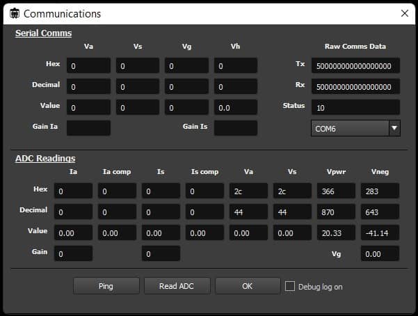
Adjust the supply voltage reading.
- Open the ‘Debug’ and ‘Calibration’ dialog boxes.
- Measure the supply voltage at the +20V test point and ground. Write the value for Vsupply down.
- Adjust the ‘Vsupply’ slider to indicate the measured value in the ‘Vpwr Value box’.
- You may need to hit the ‘ping’ button while doing this to update the Vpwr boxes.

Adjust the negative supply Voltage reading.
- Measure the voltage between ground and the -40V test point.
- Adjust the ‘Vn slider to indicate the measured value in the ‘Vneg Value box’.
- You may need to hit the ‘ping’ button while doing this to update the Vneg boxes.
Anode Supply
- First set the delay to ‘10’ in the ‘Option’ dialog box.
- Under Type Selector, choose Cal-VSupply_AorS.
- Connect a voltmeter across the anode supply capacitor C18 test terminal.
- Press “Start” three times and adjust the Va slider to read 400V + Vsupply on the meter.
- Repeat as necessary to set the slider correctly.
Screen Supply
Same as above for Anode Supply, but for the Screen Supply (grid 2), connect the meter across C13 test terminal and use the “Vs slider” to adjust the voltage in the Calibration Dialog.

To test the Anode and Screen supplies, I use probes connected directly to the corresponding header. Here are my test probes connected to the Anode test header:


Ia Anode current reading
- Connect a 10k ohm 1% resistor between the Anode and Cathode terminals.
- Monitor the Ia current value using the debug / communication dialog. Follow the procedure for Va above using the Ia slider instead. Adjust for a reading of VStart/10 mA i.e., 40mA.
Is Grid 2 current reading
- Connect a 10k ohm 1% resistor between the Screen (grid 2) and Cathode terminals.
- Monitor the Is current value using the debug/communication dialog. Follow the procedure for Ia above using the Is slider instead.
Grid Voltages
NOTE: If you require higher accuracy with grid voltages below 200mV, read the Low Voltage Grid Accuracy Mod Page.

Connect the meter between the Grid and Cathode terminals.
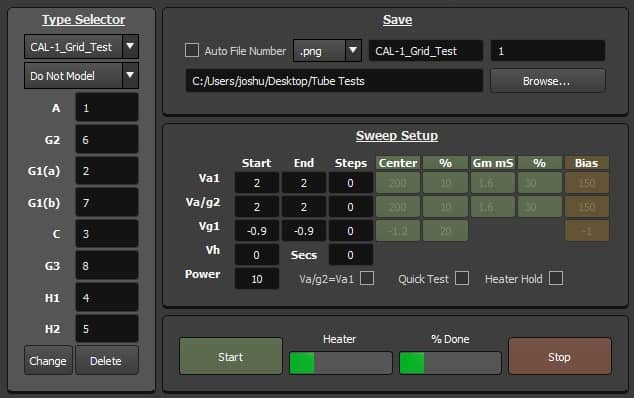
- Set the Type Selector to CAL-0.5_Grid_Test, press “Start” as before, target -0.5V using the Vg1 slider.
- Repeat using Type Selector set to CAL-1_Grid_Test, press “Start” as before, target -0.9V using the Vg1 slider.
- Repeat using Type Selector set to CAL-4_Grid_Test target -3.9V using the Vg4 slider.
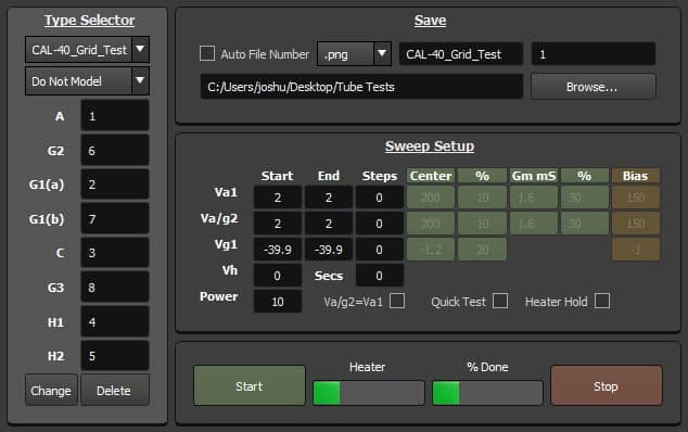
- Repeat using Type Selector set to CAL-40_Grid_Test target -39.9v using the Vg40 slider.
Grid Cal test versions can be seen below. All Cal tests are at the bottom of the Type Selector dropdown list (unless you changed the order in settings).
Note: If you don’t have the -0.5V calibration, you’re using an older version.

Low Voltage Grid (Tuning to Zero)
Whether you’re using FUtracer v7.0, or a modded v6.9, you will want to tune your glow grid voltage. Your goal is to set the idle grid to cathode voltage to zero, then test as per below. As always, follow all safety precautions.
Place your hopefully high quality DMM with the positive lead on the grid, and the negative lead on the cathode. Adjust the trimmer resistor to read as close as you can to 0.000 on your DMM. Keep in mind that the trimmer will move the voltage to positive or negative volts, and you’ll need to adjust accordingly to get to zero.
After you’ve tuned your grid-to-cathode voltage to 0, you can run a test to see how well you did. Keep your DMM leads in place, connected to the grid and cathode. Run the following sweep:
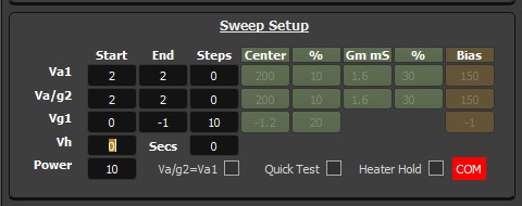
Make sure to go into options and set the delay to 10 seconds so you can see and record your voltages:

These were the test results I got on one of my FUtracers:
-002.0mV
-100.3mV
-199.6mV
-298.2mV
-396.5mV
-495.1mV
-593.5mV
-692.1mV
-803.0mV
-901.7mV
-1.002mV