Let’s get into the details of How to Build the Official FUtracer Enclosure.
Step 1: Prep the Cover
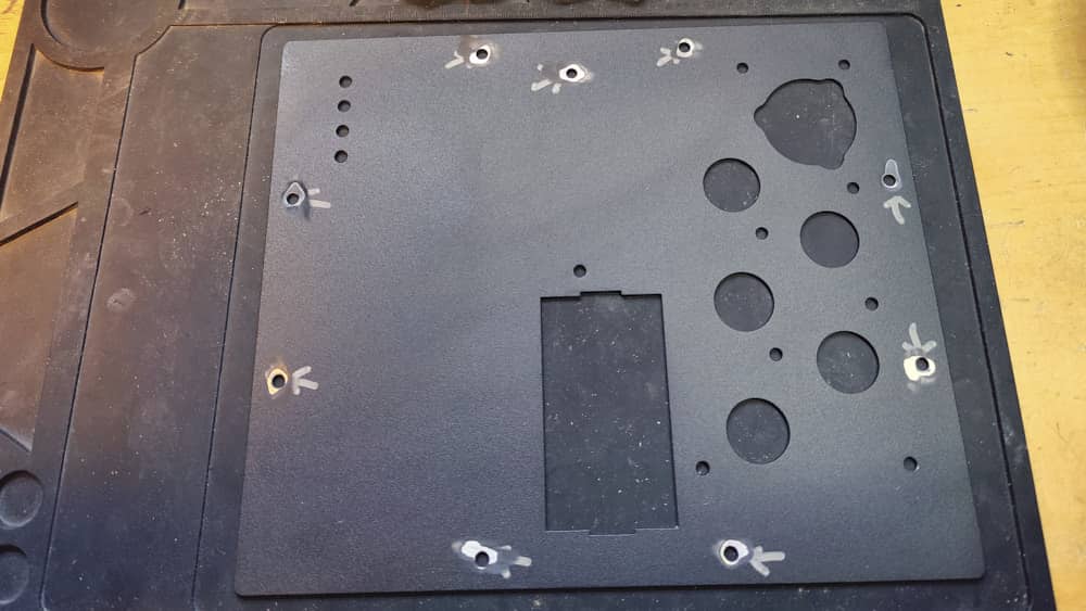
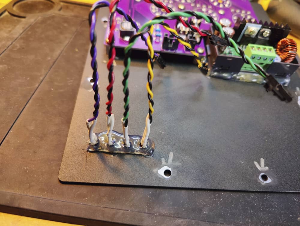
Prepare the chassis cover by removing some of the powder coating to allow the shielding and grounds make contact between the cover and the enclosure.

The top center marked hole is the ground & shielding connection for the tube socket board, and is essential for proper use of the tube tracer.
Step 2: Prep the Tube Socket Board
After all the components are soldered to the tube socket board, solder in the 7 and 8 pin sockets. Do NOT solder in the 9 pin sockets yet. Mount the 3/8″ spacers to the tube socket board.


Step 3: Mount the Tube Socket Board
After all the components are soldered to the tube socket board, solder in the 7 and 8 pin sockets. Do NOT solder in the 9 pin sockets yet. Mount the 3/8″ spacers to the tube socket board


Step 4: Solder the Remaining Tube Sockets
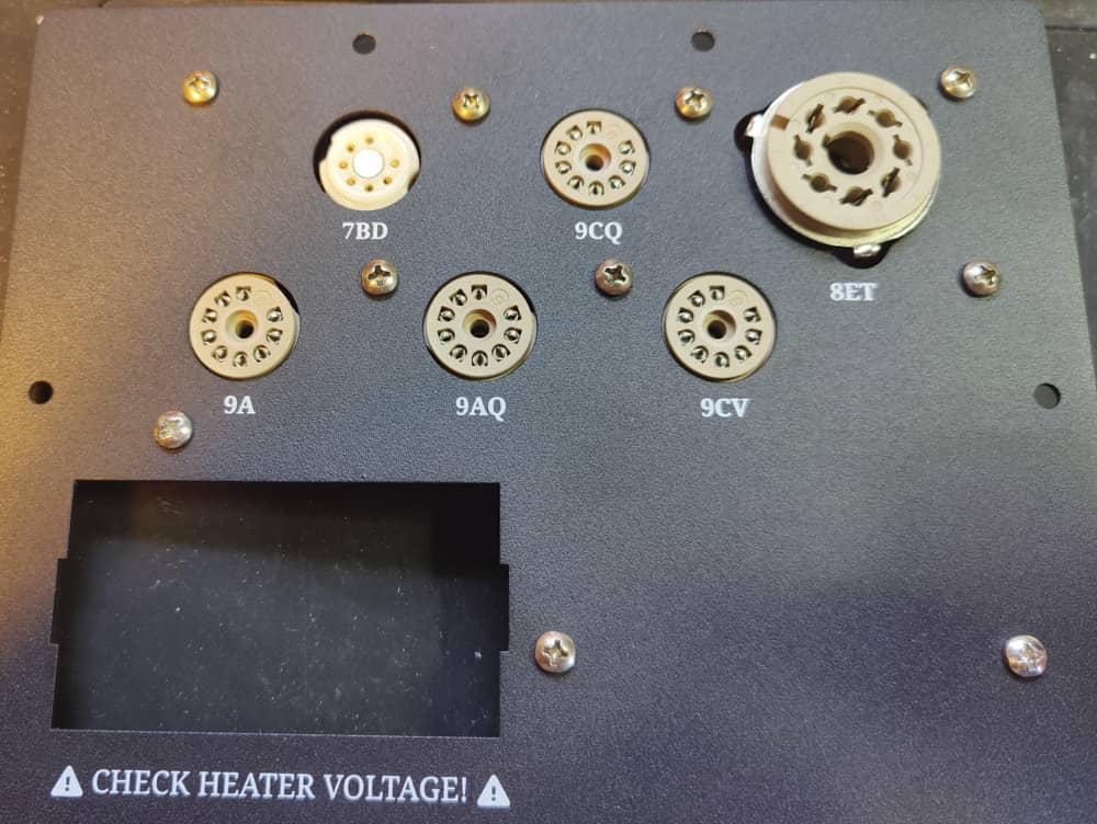
Once the socket board is mounted, the noval sockets (9 pin) should be flush against the cover. Now is the time to solder them in.


Step 5: Mount the Heater PSU
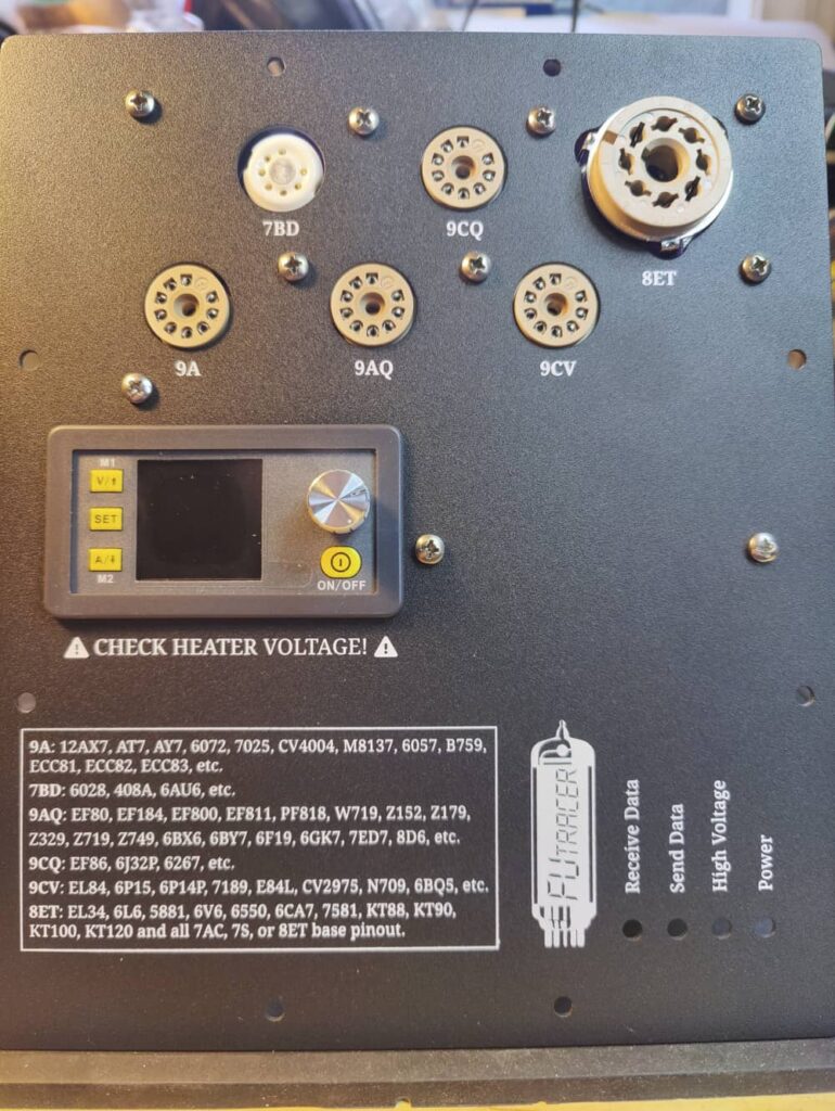
Mount the heater PSU. I like to use hot glue to secure it in place, and prevent it from sliding. I cut the edge of the hot glue to make sure it doesn’t interfere with mounting the cover plate to the bottom enclosure.

Step 6: Mount the LED Bezels
TSIA.


Step 7: Prep the LEDs
You can do this however you prefer. However, I prefer to use j-hooks. I prep the cathode of each LED first so I can’t confuse myself.
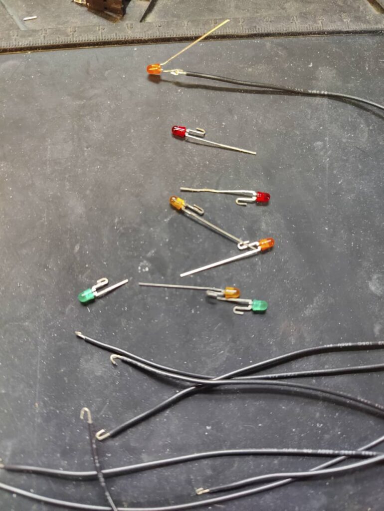

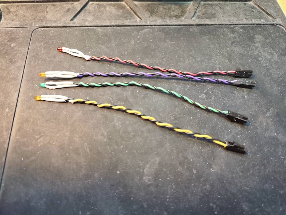
Step 8: Finish the LEDs
Once all the cathodes are wired, I color code the wires so I can see which LED I’m connecting where, without flipping over the cover. Then add the connectors of your choice. I also hot glue these, as LEDs can be annoying, regardless of the bezel type you choose. Again, cut the edge of the glue so it doesn’t interfere with the cover mounting on the enclosure.
Step 9: Inspect Your Work
After all parts are installed on the cover, inspect your work and make sure everything is clean, and there’s nothing to interfere with mounting the cover to the bottom enclosure.

Step 10: Connections
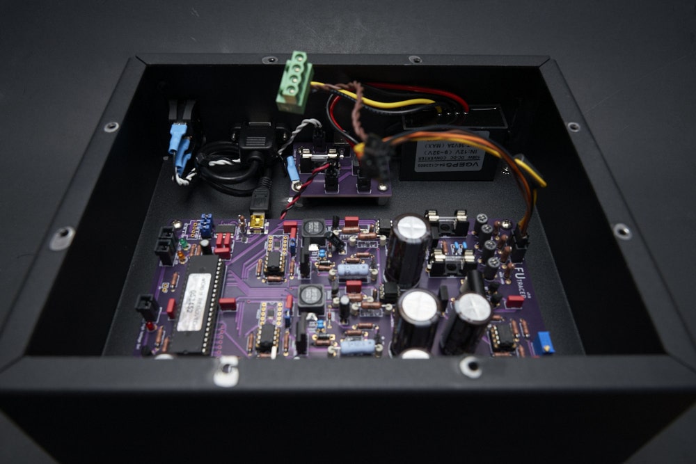
Start placing the wires that will connect power and data between the enclosure and lid parts.
Note: There are some extra parts in the following photos, as this unit is for me personally, and includes a couple experimental options. I added a step-up converter to get a higher maximum voltage from the Heater PSU. This version of the Heater PSU also has a Bluetooth connection card attached. We’ll find out in the future if we decide if it’s useful or not.
For the rest of you, I recommend sticking to what you need. Especially if you’re in a commercial or production environment and stability is important. (The same goes for your current sense resistors, stick with 6.8ohm if you need the stability and security.)

Step 11: Switch Wiring
There’s a divider on the switch between two of the Line lugs. The singled out lug goes towards the bottom. The top lug is ground, which connects via a wire to the ground screw on the PSU PCB. The source voltage from the PSU PCB switch connector goes to the middle lug, the load lug (bottom) connects to the other side of the switch connector on the PSU PCB.
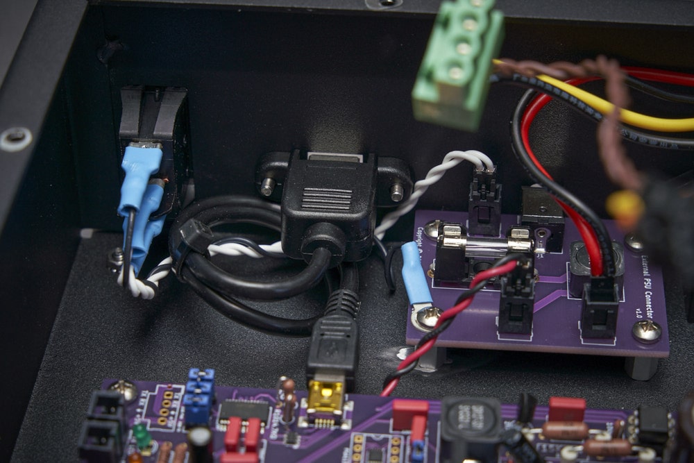
Step 12: Connect the Connection Connectors
Go ahead and plug in everything from longest to shortest. I usually start with the LEDs or ASCG board connection cable, then the Heater PSU cables. Normally, the heater PSU cables are easier to work with, but with the step-up converter off to the side, it reduced the length of the cables. Important note: If you’re going to use something like this converter also, be sure to route the wires so they don’t interfere with the cover mounting screws.


Step 13: Prosper
Use the appropriate sheet metal screws to secure the lid. Older versions might use #6 sheet metal screws, this version uses #8 sheet metal screws.
