If you need better low voltage grid accuracy below 200mV, then this mod will make that happen. It’s an optional mod, and not everybody will need this.
There is a limitation in the LM741 chip that requires adjustment for higher accuracy in lower voltages below 0.2V. There are 2 ways to go about this mod, and both have one change in common.
Step 1.
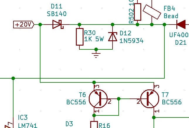
This applies to BOTH mods. Leg 3 of both BC556s (T6 and T7) will need to be connected to the 20V source before D11 SB140:
Step 2.
Grid Mod Version 2 (PREFERRED)
This option isn’t as pretty in mod format as the other version, but will eventually be made a permanent change in a future version of the FUtracer PCB. By adding a trimmer resistor between R14 and R13, we can adjust the grid to cathode voltage.

Note that the value of R13 is dropped from 12.1K to 11.7K.
Here it is in the circuit:

Obviously you will need to take care that the resistor leads won’t short anything out. I’m a big fan of heat shrink tubing.
Grid Mod Version 1
Add a 10K trimmer resistor to the LM741. Connect the sweeper to pin 4, and the ends to pins 1 and 5:

On my tracer it looks like this:

You can do it as I did above, or you can apply it below the PCB. I like this method better because you can adjust the trimmer while the tracer is built. I would recommend a multi-turn trimmer rather than the one I used above to make it easier for fine tuning.
Here it is in the circuit:

In the above photo, you can also see how I modded the emitters (BC556s) to connect the power at +20V around the SB140 anode lead.
Tuning to Zero
Now the goal with either version of the mod is to get the grid-to-cathode voltage to 0. Place your hopefully high quality DMM with the positive lead on the grid, and the negative lead on the cathode. Adjust the trimmer resistor to read as close as you can to 0.000 on your DMM. Keep in mind that the trimmer will move the voltage to positive or negative volts, and you’ll need to adjust accordingly to get to zero.
After you’ve tuned your grid-to-cathode voltage to 0, you can run a test to see how well you did. Keep your DMM leads in place, connected to the grid and cathode. Run the following sweep:
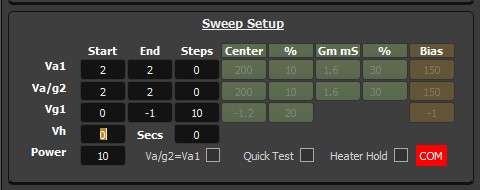
Make sure to go into options and set the delay to 10 seconds so you can see and record your voltages:

These were the test results I got on one of my FUtracers:
-002.0mV
-100.3mV
-199.6mV
-298.2mV
-396.5mV
-495.1mV
-593.5mV
-692.1mV
-803.0mV
-901.7mV
-1.002mV
That’s pretty damn good! Without the low voltage grid accuracy mod in place, the voltages under ~200mV would not have looked so pretty. I did both versions of the mod, 1 in each of my 2 tracers, and was able to get the same level of accuracy either way.
If you have an older firmware version, and can’t match the accuracy above, contact [email protected] to purchase a new firmware chip, or exchange your chip for free* (you only cover shipping fees).