This page is specifically dedicated to the FUtracer v6.9. Please confirm your tracer version before proceeding.
While building the FUtracer takes high-quality soldering skills, it’s a fairly straightforward process. Install the SMT components first, and thoroughly inspect them (preferably with a digital microscope) prior to proceeding with the rest of the through-hole components. I use solder paste and hot air to install the SMT stuff on my builds. I’ve had great success with this method, but it’s important to inspect your work thoroughly to avoid possibly melting capacitors and things if you need to correct something later. I probably don’t need to tell you how I know that.
Getting Started
Schematics
If you’ve purchased your FUtracer set, then you likely already received the password to view the schematics page. For the main PCB, it’s not really necessary to look at, just keep in mind the notes below regarding value changes. For the socket board, and EXT PSU board, you may need to view the schematics for component values.
Start by thorough cleaning and inspecting your PCB set. They should already be clean, but a little extra cleaning is generally a good idea.
NOTE: If you require higher accuracy with grid voltages below 200mV, read the Low Voltage Grid Accuracy Mod Page before proceeding with your build.
SMT Components
For SMT work, I use an Andonstar AD208 digital microscope. It does a pretty darn good job. No lag issues if you don’t max the resolution. If you have a higher budget or a fancier microscope, cool! Either way, I highly recommend something better than a big magnifying glass. Though I do love the cartoonish idea of giant eyeballs inspecting PCBs.
My soldering station is an Aoyue 2703A+ (I’ve been abusing this one for over 4 years- the last 3 stations I had from other brands didn’t last that long). The hot air works great for the SMT stuff. I use Kester EP256 solder paste – it works well but sometimes is a pain in the ass to stick at first.
Through-Hole Components
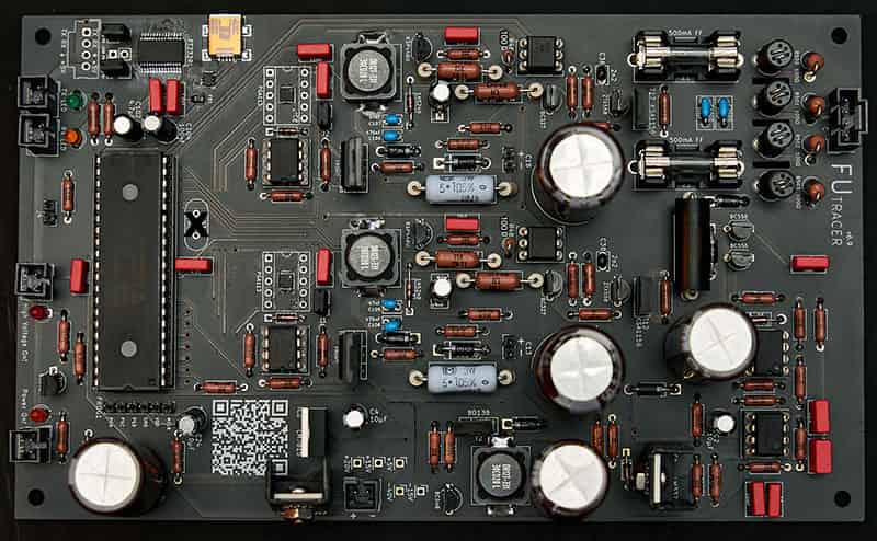
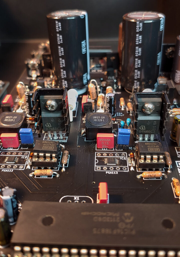
As with almost any build, you’ll want to start with smaller components, and work your way up in size until you finish with the largest electrolytic capacitors. For whatever reason, I install the DIP sockets first. I suppose it makes it easier to lay the PCB down, and make sure the diodes are placed safely. Then I install all diodes; then small resistors; then larger resistors; then the film capacitors and small electrolytics; followed by the chips; and finally the large electrolytics. It’s all fairly straight forward. Note in the photo below the placement of the ceramic spacers.
Your final PCB should look something like this:
Chip Orientation
It’s important to make sure your chips are all facing the right way before soldering or powering on your FUtracer. Refer to the following photos for the radial chips, and note the orientation for the socket chips in the image above. Double check! Twice! If you’re not sure, please ask. I’m happy to help, and I will update this site with any common questions.

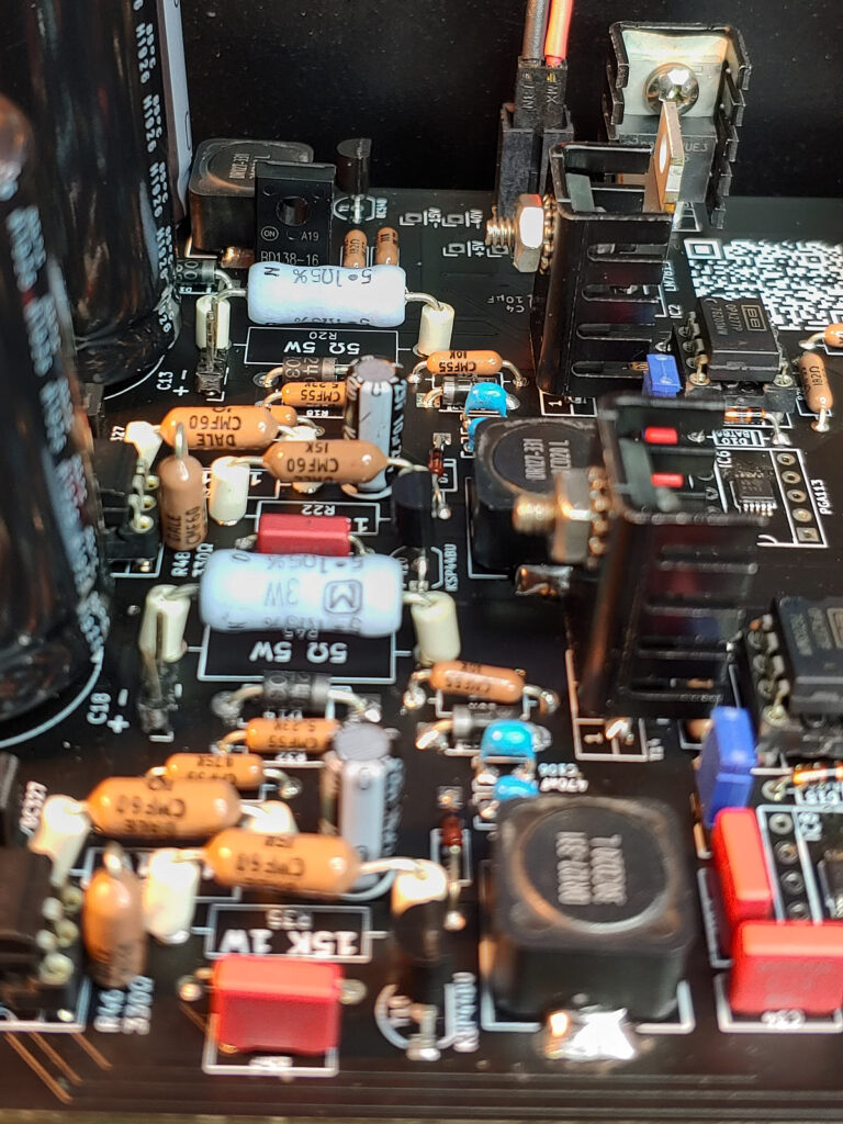
Safer Current Levels
NOTE: the IaRsense (R45) and IsRsense (R20) resistors by default allow the FUtracer to go to higher currents than what is considered safe for the KSA1156YS. If you wish to play it safer (which is not a bad idea), use 6.8 ohm resistors instead, which will give you a maximum current limit of about 529mA.
If you wish to be even safer and go below the “on paper” limit of the KSA1156YS, you could instead use 7.5 ohm resistors to get under 500mA. Whatever value you choose to go with, it is essential that you enter this value correctly, or your current readings will not be accurate.
A couple notes about the current PCBs (v6.9):
The silkscreen:
There was an error that shows R46 and R48 as 330 ohms, but they both need to be 100 ohms, and won’t work with 330 ohms in conjunction with the 4N35 optocouplers. In theory they should work that way, but they don’t. Stick with 100Ω.
Optional: 1N5993C is noted on the PCB. You can use 1N5231C instead if you’d rather pay 30 cents instead of 6 dollars. Either will work fine.
BC327 are now EoL (end of life) and can be replaced with BC559 (or BC558).
Parts NOT used:
X1, C29, and C30 are not in use, and there’s no point in installing them. I left them on because that may change in the future, but chances are they’ll eventually be removed entirely.
The next batch of PCBs will reflect the silkscreen corrections.
The External PSU Connection PCB
The FUtracer is designed to work with a 20V laptop power supply. The PSU PCB is really straight forward. The main PSU I’m using is this 20V laptop style supply: https://www.amazon.com/dp/B07RDPQ2GW/ – I clipped the end off of that and swapped it with a standard barrel plug, and covered it with some heat shrink for my tester. I don’t get a commission from that link, so get whatever you want. Though that one is inexpensive and has worked very well for me. There are three connection points on the PSU. 1 is for an external switch, and the other 2 are 20V DC outputs. One is for the main PCB, and the other is for your heater PSU (see below).
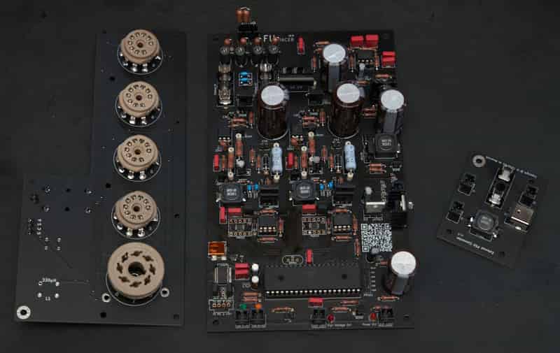
Tube Socket PCB
There are two tube socket options. One is mostly SMT, and one is only through-hole components. You can choose either one or both depending on your preferences. I prefer the SMT version because it is obviously much shorter with the SMT components compared to the fairly tall through-hole stuff. Either works very well.
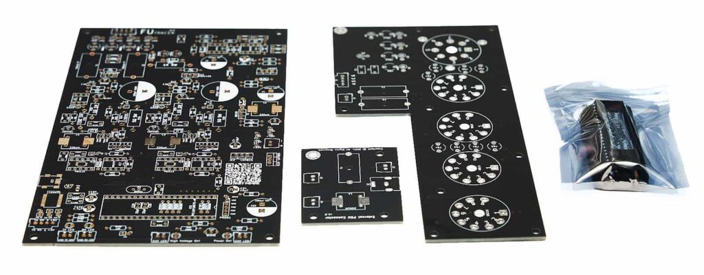
Here’s the through hole build:
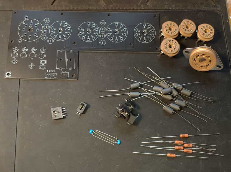
Above is all the components needed to make the socket board. I suggest that you solder in the tube sockets after dry-fitting the board to your enclosure. You should probably solder in the octal socket ahead of time, since that one can be trickier to line up the pins correctly. If you opt to run wires instead of using PC-mount sockets, be very careful to keep them as short as possible. Crossing the wrong wires could potentially cause issues.
Here’s the socket board built minus the sockets:
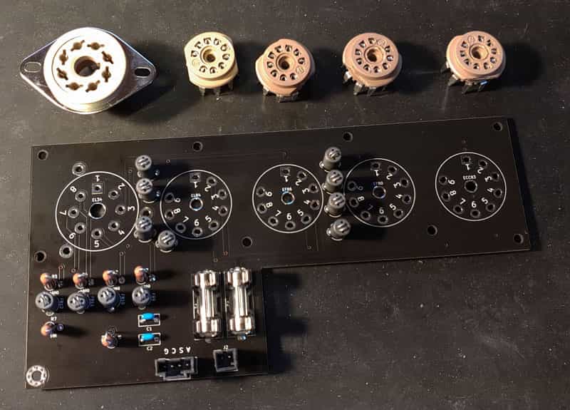
The sockets get installed on the other side.
NOTE 1: There is a 1K resistor (R6) on the socket board connected to the Screen. Only install this if you’re having trouble with parasitic oscillations. Use a jumper here instead.
NOTE 2: 4 of the mounts for the socket board either need to be nylon, or use nylon washers to isolate the board. This is only an issue if you overtighten the screws and the mounts damage the solder mask. Which I did on my unit after assembling and reassembling too many times with a power tool. For most people, this may not be necessary, but I prefer to err on the side of safety. The BOM has been updated with suggested mounts, 4 nylon, and 6 metal.
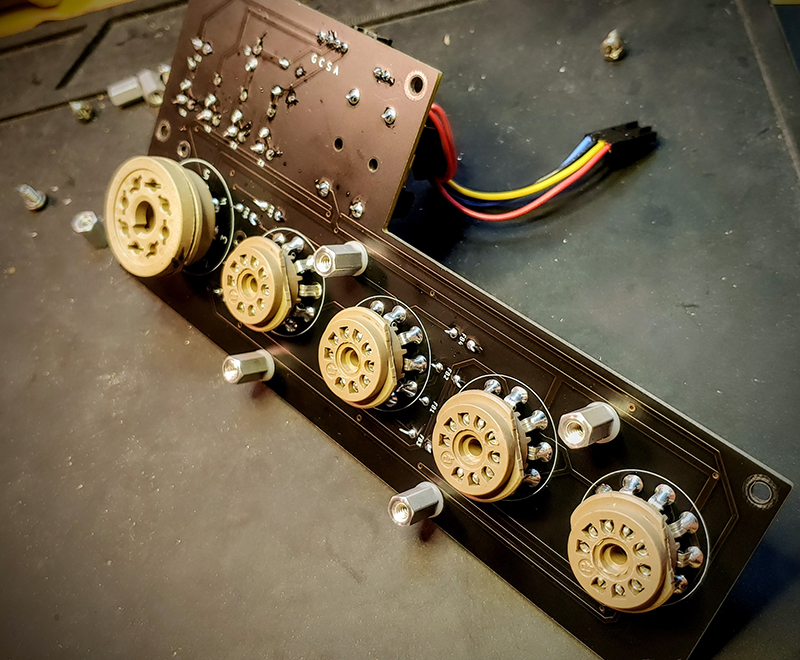
This is the placement for the nylon standoffs or washers:
Socket Board Connection
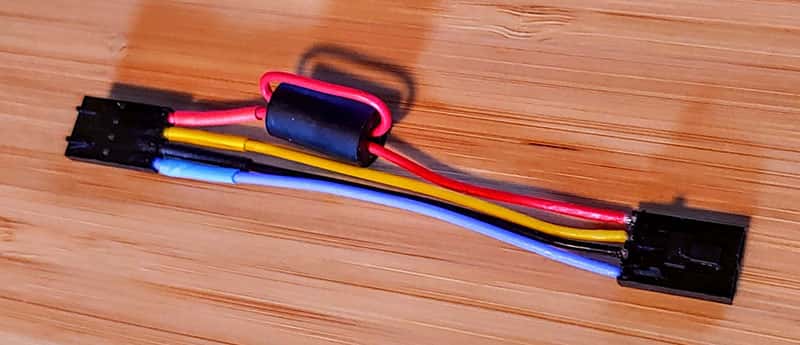
For your connection between the main PCB and the tube socket board PCB, I recommend placing a ferrite bead on the Anode wire and wrapping it through like this:
The Heater PSU
It’s important to note that there is no heater power supply built in to the PCB. You must use an external PSU. This is what I use for the heater power supply: https://www.amazon.com/dp/B01LWXAC5E. I’ve been using that for a few years, and it works great. I’m sure there are other similar supplies that would also work well. I limit the current to 2A in my presets, and you should be sure to limit the current to whatever fuse rating you use on your Socket Board PCB. Click here for the instructions for the PSU linked above.
FUtracer BOMs
Assuming these don’t get hacked, they should be fairly accurate as to what you need. The main PCB has a couple different options for a couple parts. For example, the BAT86S is EoL, so there is a second option available. However, there is plenty of stock of them, so they were not removed from the list yet.
Through-Hole Tube Socket Board
Please Note: There are a number of items including tube sockets, general hardware, etc. that are not included in the BOMs. I use Belton Micalex PC Mount Tube Sockets. You can use those, or find another product with similar pin spacing.
Enclosures
Use a metal enclosure that can act as a ground and shield. Here is an Enclosure Option (will need some modification depending on your layout). If you use a painted or powder-coated enclosure, you will need to sand down the finish where the ground and shield screws mount. Failure to do so could be dangerous and/or prevent the device from functioning.
Schematics
For now, schematics are not public. If you need a schematic, and you’ve already purchased your FUtracer PCB set, you can email support at futracer dot com to request the schematics you need.
Parts Drawings
Here’s a few drawings for some of the off-PCB parts. You don’t have to use these parts specifically, but if you’re going to PC-mount the sockets, you will need them to be similar dimensions to the Belton sockets.
Belton Octal Socket (Note: this is the same dimensions as what I use, but the model I’m using doesn’t have the extra support mounts that the PCB is equipped for. I’ve only seen them listed in the UK.)
Power Jack – this drops in directly to the external PSU PCB. If you want to use something else, make sure it matches.